


 Matric Group
1 min read
Why PCB Failures Happen: 6 Common Causes OEMs Can Prevent
Printed circuit boards (PCBs) are the backbone of nearly every electronic device. From industrial controls and medical equipment to defense systems...

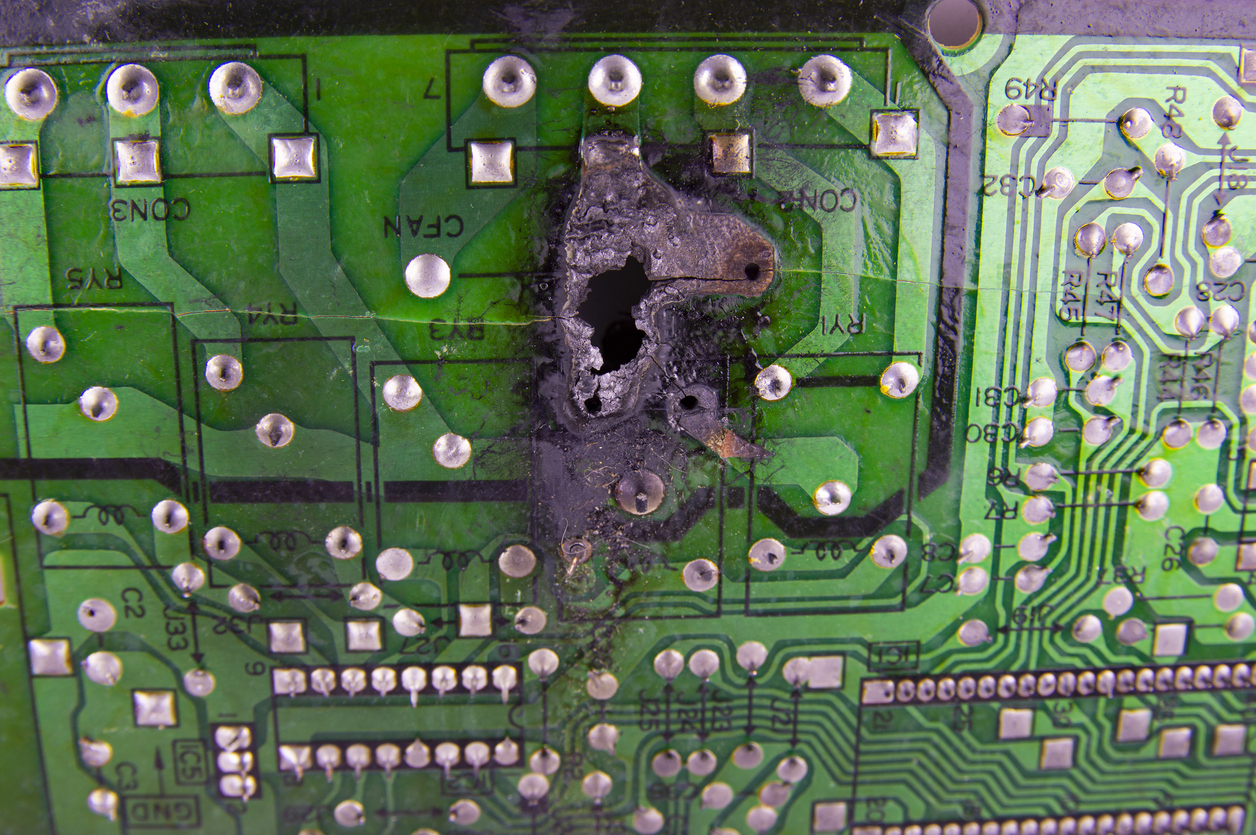
Overheating in your Xbox or iPad? Inconvenient. Overheating in the gas meters, mining equipment, or pacemaker you designed? More than inconvenient.
The quality of printed circuit board (PCB) thermal management in your product design can determine its success or failure. PCB components are prone to deterioration because of heat, which can undermine your product’s functionality and life cycle. In mission-critical aerospace or medical equipment, outright failure could be catastrophic.
Here’s how to reduce heat in PCB designs and be known as a maker of trustworthy, long-lasting products:
How much heat are you looking to remove, and how will each design element (including the end-use environment) affect it? From there, you can determine how much effort to invest in these fixes:
With careful circuit design, the amount of heat to be dissipated can be understood and minimized. Power circuits can be designed for maximum efficiency. A circuit simulator program can be used to calculate estimated power dissipation.
Passive PCB heat dissipation techniques are not enough in a layout that produces a lot of heat. It's up to you, the designer, to incorporate dissipating features like:
Temperature fluctuations are inevitable when current passes through PCB components. One key PCB design consideration is to ensure the material supports the expected working temperature.
PCB materials usually comprise substrates and laminates. Both are customizable according to need and, when coupled with a high-dialect constant board, make the best PCB thermal management material.
(Related blog: Best PCB Substrate Types Your Board)
Copper, as you know, is an excellent conductor of heat. That explains why large copper planes increase the capability of a surface to disperse heat. Your best for dissipation is adding these to the PCB’s upper and lower layers, where heat exchange is greater, but internal copper planes work OK too.
You’ve probably also heard of FR-4 (flame-retardant Level 4) material and its use in many circuit types. However, more specific substrates are a must for some applications:
Another board manufacturing method called MCPCB (metal core PCB) combines substrate materials with differing thermal conductivities alongside metal planes (usually copper). This technique, possible on both the upper and lower layers of your board, is common in lighting applications with power or very bright LEDs.
The more prepreg material exists in your layout, the harder it is to eliminate thermal stress. The aforementioned MCPCB trick uses a thermally conductive prepreg between layers to draw heat from components and route it toward copper planes.
In laminates, consider these heat-resistant properties, especially if the end use will involve extreme temperatures:
While costly, Rogers PCB laminates have a high dielectric constant for heat dissipation superior to FR-4 materials’. As a side bonus, these laminates remain efficient as temperature and frequency vary.
Increasing the distance between components promotes safer PCB heat transfer. This allows you to avoid PCB design mistakes like heat hotspots.
Ask yourself:
Powerful components mounted near the edge accumulate heat and raise the local temperature. Place high-power components – think microcontrollers and processors – at the center of your PCB. A dissipation-friendly layout is a balancing act, though – try to spread high-power components evenly across the layer.
Heat affects some components more than others. Route high-current traces away from sensitive components like sensors and operational amplifiers.
You can easily find recommended spacing standards in the IPC-2221 PCB design guide. The proximity factor is tough to work around in smaller devices, but using smaller components and PCBs can help.
At the board level, sinks, pipes, and fans aren’t an option in small devices. The only option is to increase the board’s heat conductivity – which you can do with a thicker board and more surface area.
At the component level, copper is king. Adding thick copper traces can increase your PCB’s maximum current and temperature, especially in power-focused applications. Heavy copper technology uses traces up to 2.1 mm thick (compared with standard tracks of 0.105 mm). Your selected trace thickness should clear a path for passing current. Resistance in copper traces and vias accounts increases heat production and reduces power.
The thickness and width of copper pads also impact the effectiveness of PCB thermal design. Heat dissipates directly toward the top layer, so your top copper pad needs enough thickness and area to spread heat safely.
Enclosure thermal design is all about optimizing the movement of air.
Since the housing goes on last during assembly, it’s natural to think of its design last. However, designing your electronic enclosure concurrently with the “guts” inside can improve:
Industries that use sensitive or outdoor equipment (such as telecommunications) must especially pay attention to enclosure design.
To cut the chances of degrading your components, build an open electronic enclosure that allows air in and out. In enclosed spaces, you may opt for forced-air dissipation techniques like surface-mounted fans. Designs with high expected heat levels may need multiple fans to keep the electronics safe.
Finally, if the enclosure will be exposed to sunlight, use a surface finish that won’t absorb heat.
Overheating is a disastrous result in any high-reliability electronic design. It’s a lifesaver (literally, in some cases) that there are so many tricks for dissipating heat – even a few we didn’t have space to mention!
To get started on improving your design, consider using a PCB heat dissipation calculator. It’ll determine your expected heat load so you can add the appropriate thermal management in your PCB design.
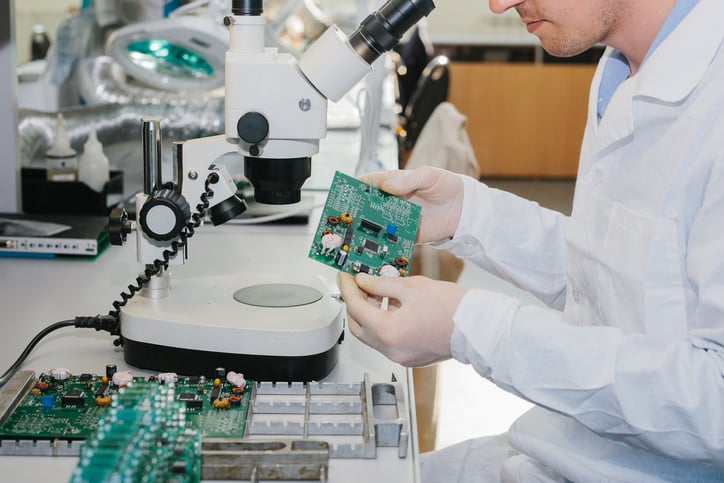
To learn about the critical PCB testing methods that prevent product failure (like component burnout), download this free e-book:
1 min read
Printed circuit boards (PCBs) are the backbone of nearly every electronic device. From industrial controls and medical equipment to defense systems...
1 min read
“How will my idea go from conception to finished product at your company?” It’s a question we hear a lot, and a good one. It’s natural to want to...
1 min read
Bringing a new electronic product to market is no small feat. From intricate circuit board designs to complex cable assemblies, every detail must...