


 Matric Group
1 min read
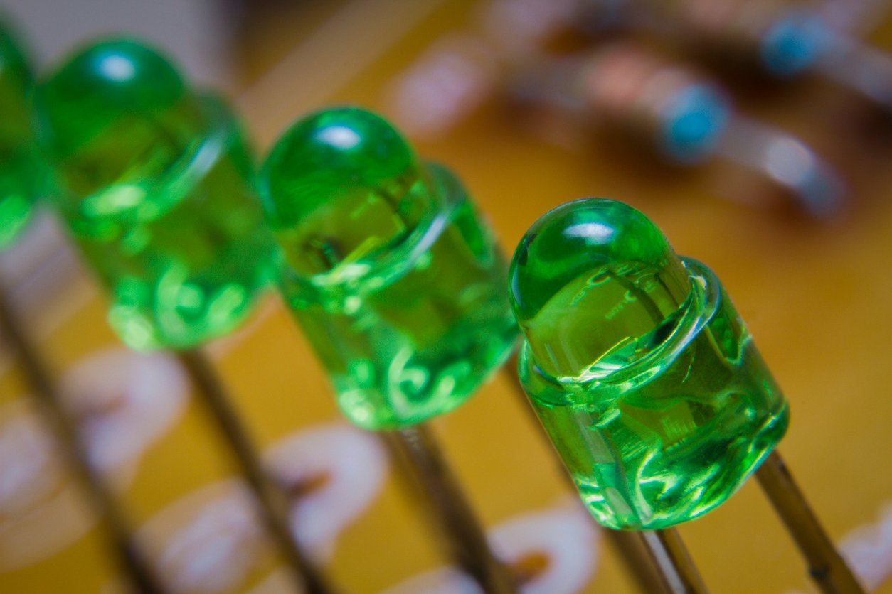
LED PCB Design for Safety
At this point, we’re all familiar with light-emitting diode (LED) lights. From the bright, efficient bulbs replacing the old filament lamps, to the...
1 min read
At this point, we’re all familiar with light-emitting diode (LED) lights. From the bright, efficient bulbs replacing the old filament lamps, to the...
1 min read
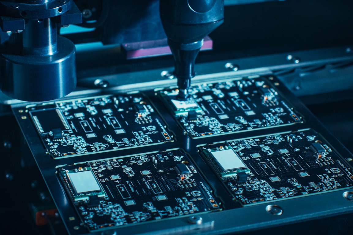
Printed circuit boards (PCBs) are the backbone of nearly every electronic device. From industrial controls and medical equipment to defense systems...
1 min read
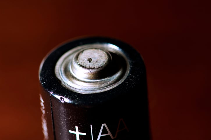
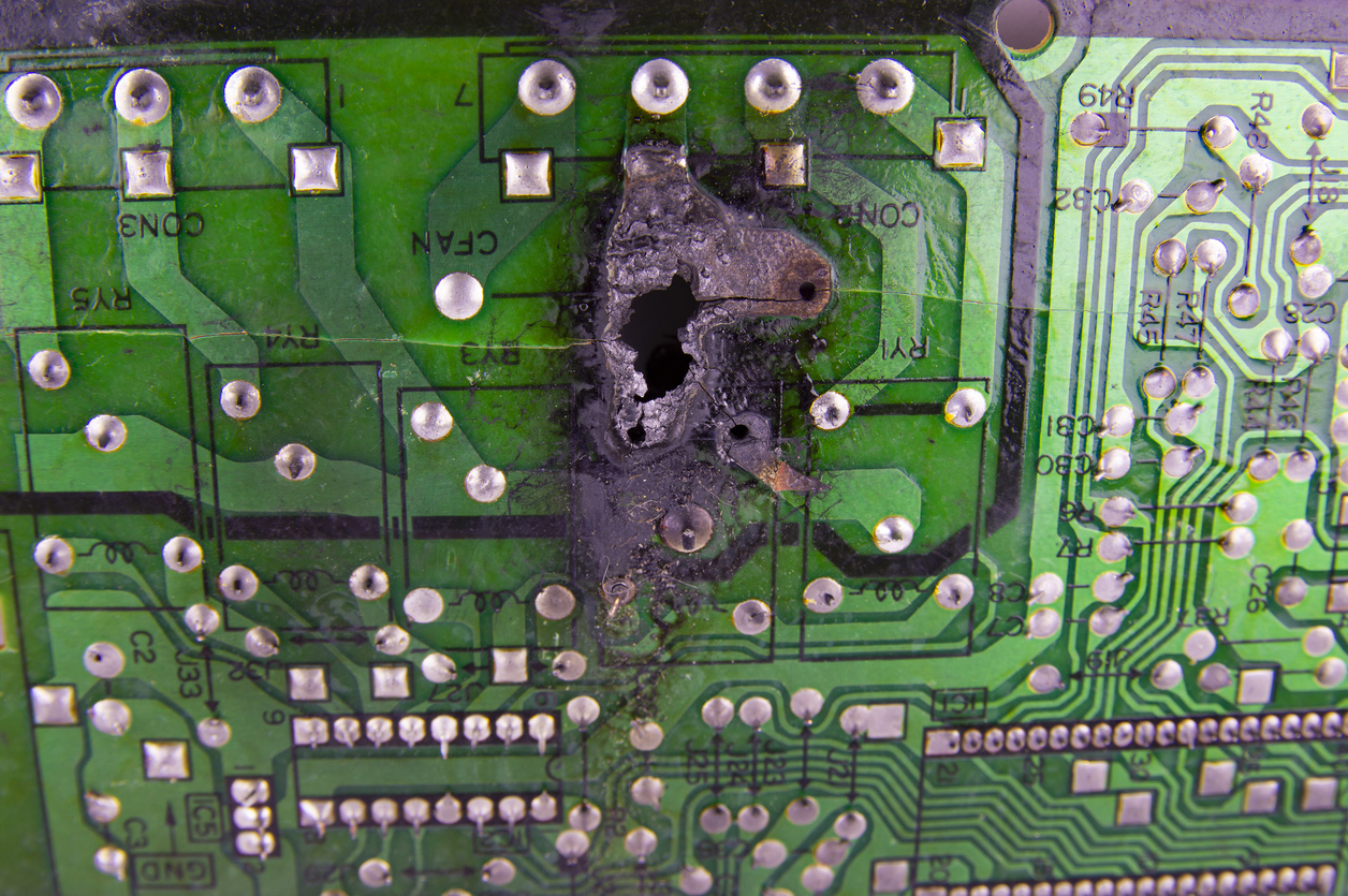
When turned on, electrical equipment generates sparks. Some equipment generates heat that can lead to ignition, while electric arcing occurs...