Common PCB Defects: What Causes a Circuit Board to Burn?
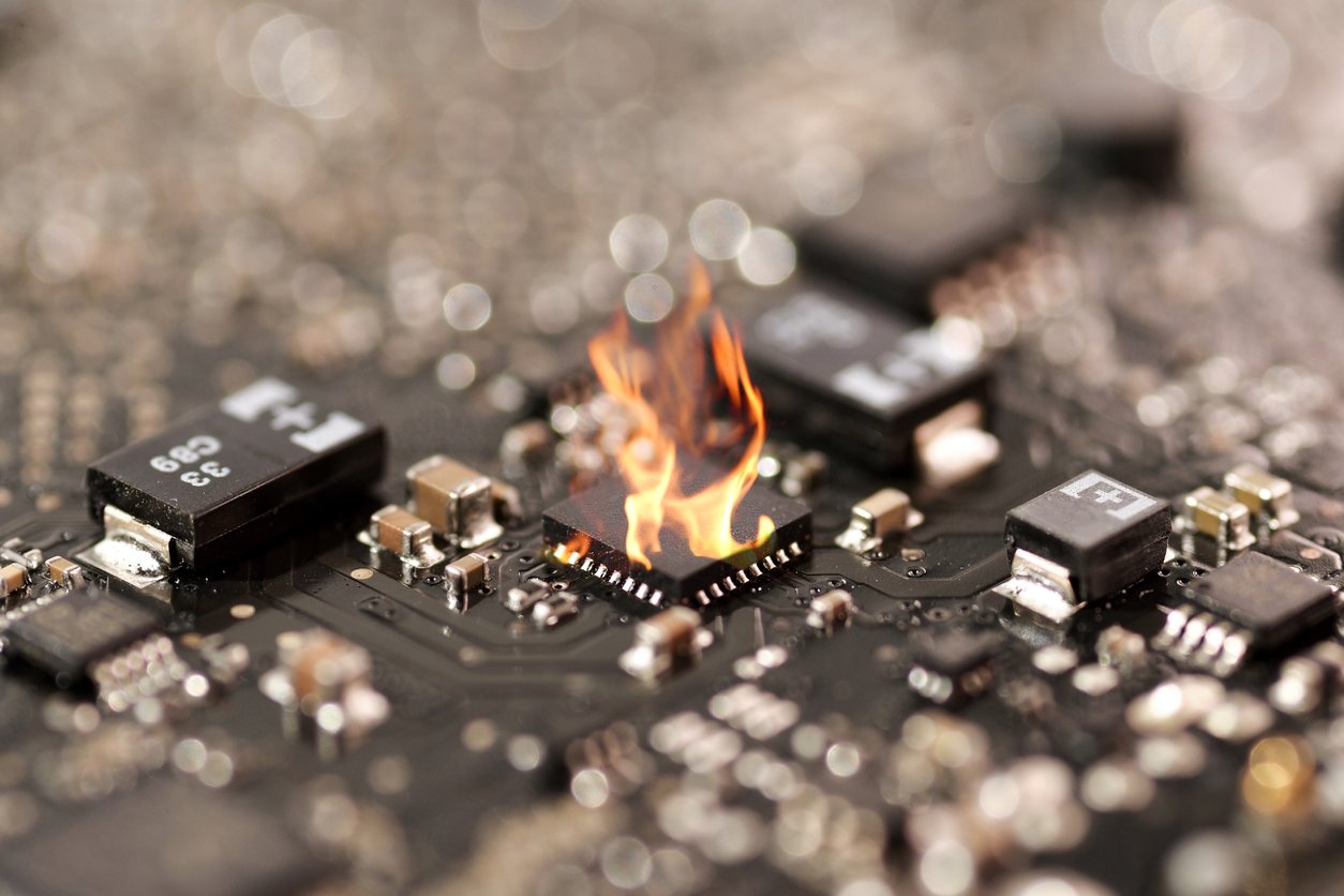
While there are many common printed circuit board defects, one of the most notorious is burnt components. It's also, unfortunately, one of the most...

As electronics have become increasingly embedded in our day-to-day, the manufacturing process for printed circuit boards (PCBs) has adapted. Electronics have become smaller and smaller, and the PCBs that go in those products have had to shrink to keep up. The demand for tiny PCBs has led to a drastic increase in the use of surface mount technology (SMT) -- which has taken over the traditional through-hole manufacturing process that dominated electronics into the 1980s.
There are many advantages -- and a few drawbacks -- to surface mount assembly that are worth considering as you plan your own PCB manufacturing needs. While the smaller profile, lower cost, and increased efficiency of surface mount assembly are ideal for most applications, there are certain situations where the improved durability and higher power capacity of through-hole assembly is preferable.
As the Internet of Things (IoT) grows with each new iteration of electronic devices (just look at all the “connected” stuff in your home), components continue to shrink. In turn, PCB layout needs to take up less space in the enclosure, too. So the battle comes down to through-hole vs. surface mount.
Most new projects are migrating toward surface mount assembly. However, there are some situations where through-hole assembly makes for a better product.
Let’s look at some of the main differences between the two methods.
Pros and cons of though-hole technology assembly::

Pros and cons of surface mount technology (SMT) assembly:
Despite its superiority, SMT is typically most cost-effective than surface-mount assembly for a variety of reasons. It can be automated, it’s easier to find components -- because demand is high -- and you can produce at a much higher volume.
The cost and speed improvements offered by SMT are undeniable. It’s the main reason designers are flocking away from through-hole.
Testing methods do need to be adapted to test SMT boards. For example, if your electronics contract manufacturer doesn’t have x-ray testing capabilities, you may have a problem. As boards continue to shrink, we’re seeing technologies like ball grid arrays (BGAs) and QFN (quad flat no-leads package) devices incorporated.
The idea is that you can save even more real estate if you put things underneath the board. But to test those kinds of boards you need x-ray capabilities. That way your contract manufacturer can inspect any joints underneath the board.
Testing on through-hole boards can present challenges as well. For example, if the PCB is large or unique in shape, it might be harder to test. Specialized testing requires more labor and therefore a higher price.
If your project sounds anything like what we just discussed, you may want to take it to a contract electronics manufacturer that’s well versed in PCB testing and design assistance.
At Matric, we’ve gone from 20% of jobs being SMT twenty years ago to 80-85% today. The through-hole work of today is mostly dinosaur projects meant to keep a product alive for legacy customers.
Redesigning an electronics product sounds scary, but so does becoming extinct. An experienced ECM can minimize the hassles of obsolescence for customers by moving them toward SMT PCB assembly services. Your manufacturer should help you design an SMT version of your current through-hole design. The right partner will save you money and frustration as it becomes ever harder to find through-hole components.
If you have a through-hole PCB design you think is endangered, consider asking your provider of PCB layout services whether it’s capable of making the conversion.
Editor's Note: This post was originally published in April 2019 and has since been updated.

While there are many common printed circuit board defects, one of the most notorious is burnt components. It's also, unfortunately, one of the most...

When designing solar-powered embedded systems intended for outdoor applications, durability, performance, and energy efficiency are a perfect storm...

If you’re considering switching an existing electronic product design from through-hole technology to surface mount technology (SMT), you’ll want to...